BackIndex Page
Small Drone Power Core — Investor & Development One-Pager
Ioncore logoIoncore Energy
Small Drone Power Core Investor & Development One-Pager • No equity terms
Early Investment & Development (Investor-Ready Summary)

Compact turbine-driven power module for endurance-focused UAV platforms

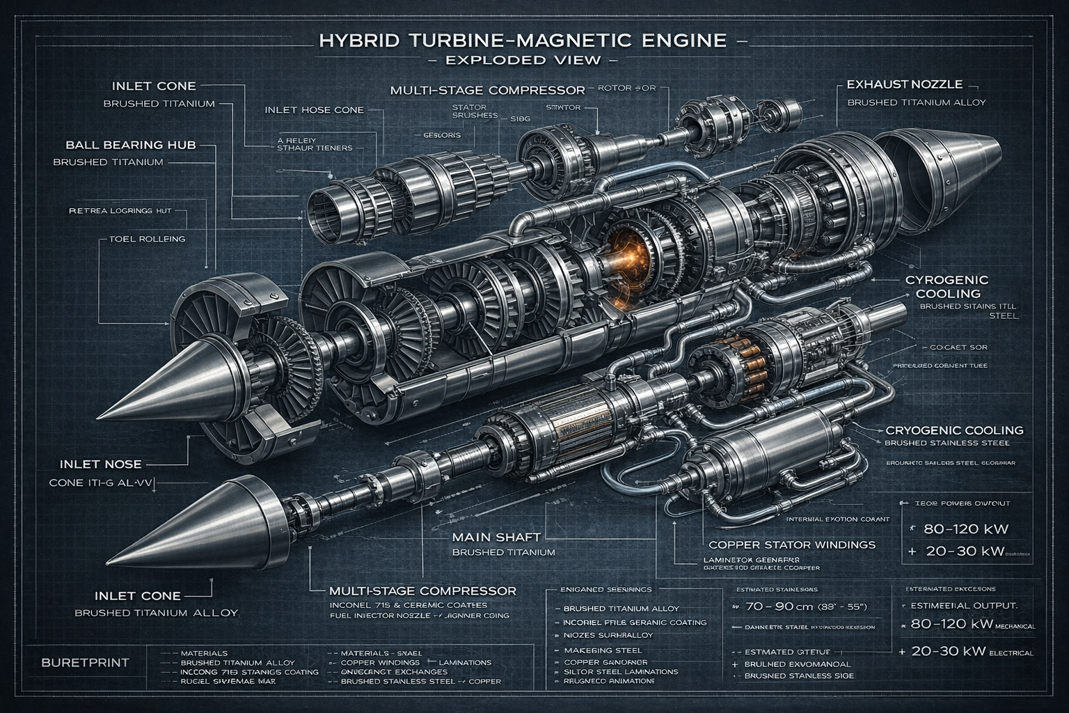
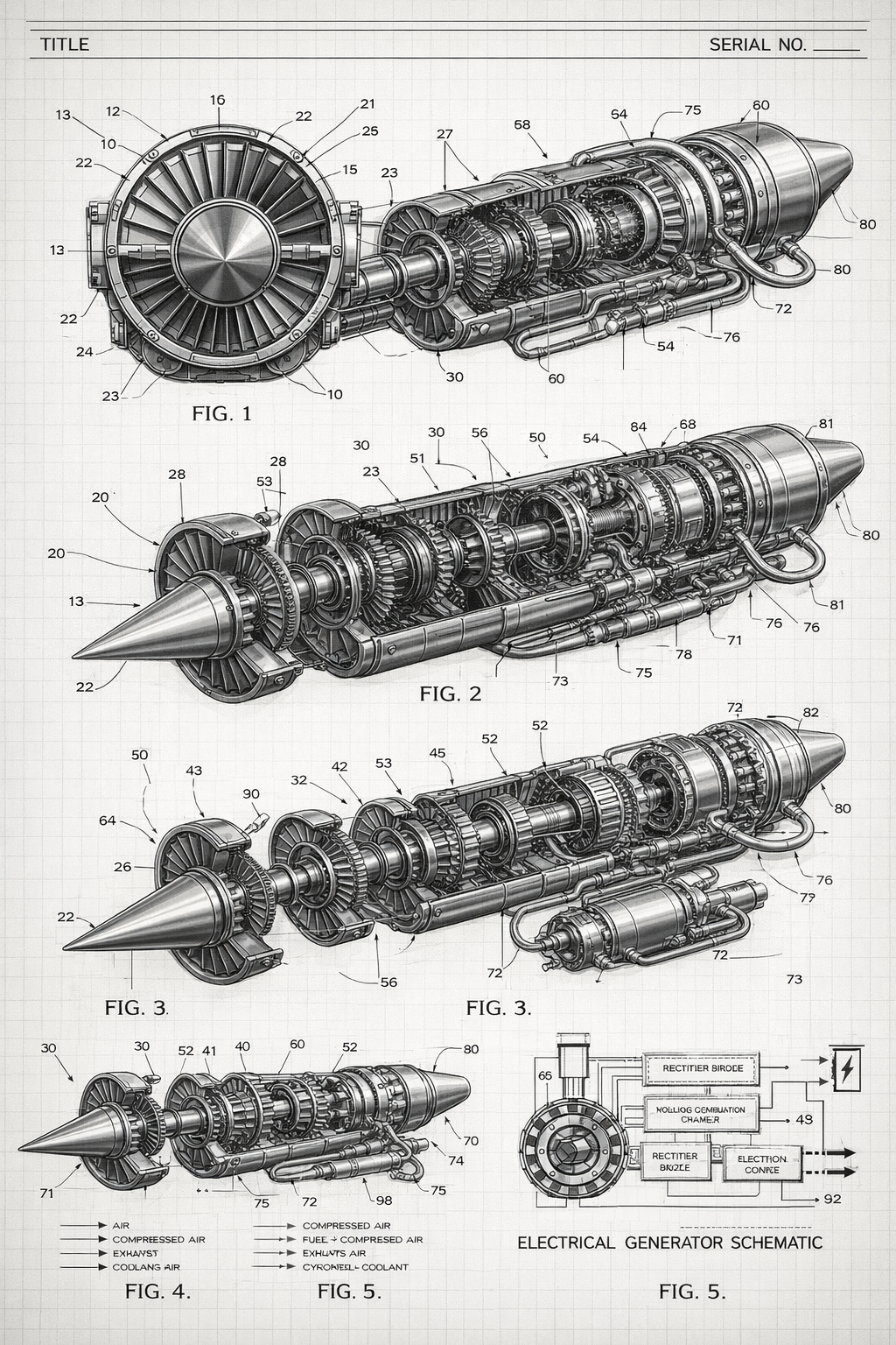
We’re developing a Small Drone Power Core: a compact turbine energy core with an integrated magnetic generator, a regulated DC power stack, and thermal management—engineered as a single, testable module.

This is built like a product program: clear interfaces, safety logic, a validation plan, and deliverables that translate into prototype readiness and scalable manufacturing.

Modes: Turbo-Electric / Turbo-Shaft Output: Regulated DC bus Baseline: Liquid cooling Options: Cryogenic loop, magnetic inertia
Performance transparency: All performance numbers remain targets until validated via component maps, thermal limits, and instrumented testing. The roadmap below is designed to turn targets into verified specs.
Jump to Partnership Ask See Pricing

What’s inside the module

  • Turbine energy core Brayton cycle
    Inlet → compressor → combustor → turbine → exhaust
  • Shared-shaft magnetic generation 3-phase
    Rotor + stator windings with high-speed packaging
  • Power electronics stack AC→DC→Reg
    Rectifier, DC link, regulation, protected distribution
  • Thermal management continuous rating
    Liquid loop baseline; advanced thermal options available
  • Controls + safety sequencing
    V/I/T/RPM sensing, fault handling, safe shutdown
Design philosophy: treat the engine as a complete power architecture—so integration, safety, and continuous performance are engineered in from day one.

Ioncore branding + shared engineering assets

This page now uses Ioncore branding and includes the shared turbine imagery pack from the repository for visual consistency across the brochure suite.

Ioncore hybrid turbine concept rendering 1 Ioncore hybrid turbine concept rendering 2 Ioncore hybrid turbine concept rendering 3

The problem

Small UAV platforms increasingly require longer mission time and higher sustained payload power, but power systems often become the bottleneck due to energy density limits, thermal derating, and integration complexity.

  • Endurance ceiling mission time
    Fuel/battery capacity and sustained cruise power define total mission capability.
  • Thermal derating continuous power
    Generators and power electronics frequently reduce output under heat soak.
  • Integration friction time + cost
    Nonstandard power interfaces and safety logic slow deployment and scaling.

Our solution

A compact turbine + magnetic generation core packaged with a regulation and distribution stack that delivers a protected, integrator-friendly DC output—backed by a validation plan that produces measurable, repeatable specifications.

AIRFLOW: Inlet → Compressor → Combustor → Turbine → Exhaust SHAFT: Turbine → Common Shaft → Generator Rotor POWER: 3-phase → Rectify → DC Link → Regulate → DC Bus / Outputs THERMAL: Liquid cooling loop + sensors + control
Investment leverage: funding accelerates definition, testing, and iteration—moving the program from design targets to verified continuous ratings and integration-ready interfaces.

Turbo-Electric mode

Turbine drives generator → regulated DC bus → propulsion motor(s) + payload.

  • Flexible packaging airframe fit
    Place generator/motors where they best serve balance and layout.
  • Clean DC architecture stable bus
    Regulation + distribution designed for predictable bus behavior.
  • Multi-motor ready distributed
    Supports distributed propulsion layouts without mechanical complexity.

Turbo-Shaft mode

Turbine drives propulsor directly (optional auxiliary DC for onboard systems).

  • Fewer conversion steps efficiency
    Direct mechanical power path can reduce conversion losses.
  • Simpler thrust delivery prop/fan
    Conventional propulsor integration pathways.
  • Optional onboard DC hybrid
    Aux generation supports avionics and payload systems.

Pricing guide (development + units)

Pricing below reflects a doubled baseline planning guide. Final quotes are scoped to requirements and validation needs.

Development packages (NRE) doubled
Package Includes Typical Range (USD)
Concept Package Web graphics, high-level renders, diagram set, requirements outline. $25k–$125k
Engineering Definition Pack BOM v1, interfaces, controls outline, safety plan, simulation runs, patent-style diagrams. $125k–$600k
Prototype Development (Alpha) Generator bench testing + power stack bring-up + thermal loop validation. $600k–$2250k
Prototype Development (Beta) Integrated run program + endurance validation + iteration & reliability improvements. $2250k–$7.5M
Unit pricing (Core + Power Stack + Safety distribution) doubled
Volume Notes Unit Price (USD)
1–5 units (prototype) Hand build, test support, early validation overhead. $125k–$400k
10–50 units (low-rate) Stabilized supply chain, basic fixtures, QA flow. $60k–$175k
100+ units Yield improvements, cost-down revisions, production QA. $30k–$85k
Advanced option adders doubled
Option What it adds Prototype Add-On Low-Rate Add-On 100+ Add-On
Liquid cryogenic thermal module Two-loop thermal architecture: insulated tank/lines, cryo-to-secondary HX, controls & safety relief. +$40k–$175k +$15k–$75k +$8k–$40k
Magnetic inertia module Flywheel + magnetic bearing assist for transient smoothing and stability; includes containment implications. +$50k–$225k +$20k–$90k +$10k–$50k
What drives cost: high-RPM rotor/containment + balancing, hot-section materials, power electronics thermal design, validation time, and QA/yield.

Roadmap

  • M1 — Baseline lock definition
    Architecture, interfaces, BOM v1, figure pack, capability model assumptions.
  • M2 — Bench power validation electrical
    Generator + rectifier/regulation thermal behavior, load-step response, protections.
  • M3 — Rotor stability envelope mechanical
    Balance, vibration vs RPM, bearing temp, overspeed shutdown validation.
  • M4 — Controlled light-off combustion
    Stable ignition, temperature stability, safe shutdown sequencing.
  • M5 — Endurance validation continuous rating
    Continuous vs peak confirmed with heat rejection and logged data.
  • M6 — Pre-production plan scale
    QA checks, assembly steps, cost-down roadmap, supplier strategy.

Validation plan (high level)

  • Bench: generator + power stack
    Voltage vs RPM, rectifier heating, ripple, regulation stability, fault handling.
  • Thermal: continuous rating
    Cold plate + coolant loop characterization, derating curves, heat rejection limits.
  • Integrated: spool + combustion
    Light-off control, temperature stability, vibration envelope, safe shutdown.
  • Endurance: mission profile
    Cruise-power fuel burn and sustained output validation with instrumentation.
Deliverables to partners: test reports, updated spec sheet, BOM revision, integration notes, and a production-readiness plan.
Instrumentation targets (examples): - RPM, temperatures (stator/rectifier/DC-DC), coolant in/out - Bus voltage/current, ripple, load steps - Vibration (accelerometers), optional pressure sensing

Partnership ask (no equity terms)

We’re looking for early partners to accelerate definition, validation, and prototype readiness. Engagements can be structured as development sponsorship, prototype pre-orders, or integration programs.

  • What funding supports use of funds
    Rotor dynamics + containment, power electronics iterations, thermal validation, instrumentation, and manufacturing planning.
  • What partners receive deliverables
    Early interface definitions, milestone reports, prioritized integration support, and prototype allocation (as available).
  • Partner fit who we want
    UAV platform builders, energy integrators, and organizations needing compact regulated DC power modules.
Fast scoping: A 30–45 minute discovery call to align on power class, DC bus target, and mission profile. Then we deliver a scoped development plan and timeline.
CONTACT - Name: Jodel Chad - Email: jodelchad@chaines.io - Handle: @jodelchad REQUESTED INFO (to scope quickly) - Target continuous kW (e.g., 5 / 10 / 20) - Turbo-Electric or Turbo-Shaft (or both) - DC bus target (48–120V or 300–450V) - Desired mission profile (cruise power + duration) - Environment constraints (temp, altitude, duty cycle)
Important: This page intentionally contains no equity/share terms. Partnership structure is handled separately.
This one-pager is informational and subject to change. Any commercialization or performance representation is contingent on engineering validation and compliance with applicable safety and regulatory requirements.
Ioncore Energy Ioncore Energy Magnetic Inertia Systems